TOGOAT
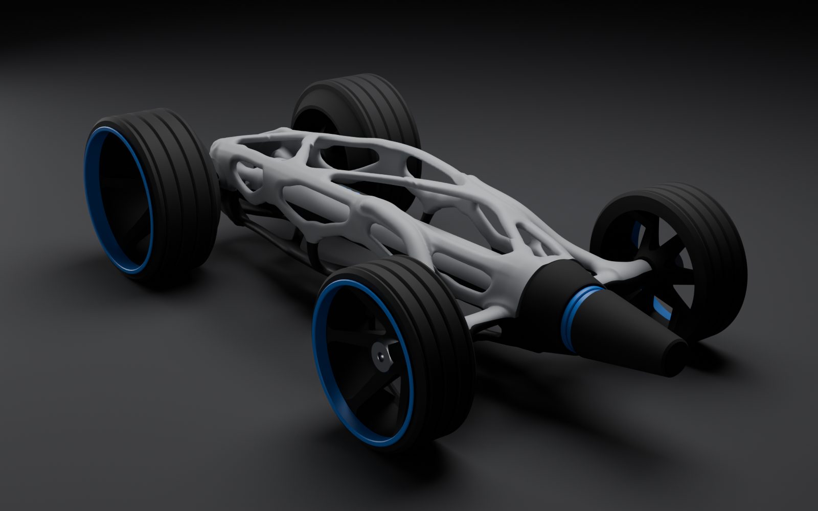
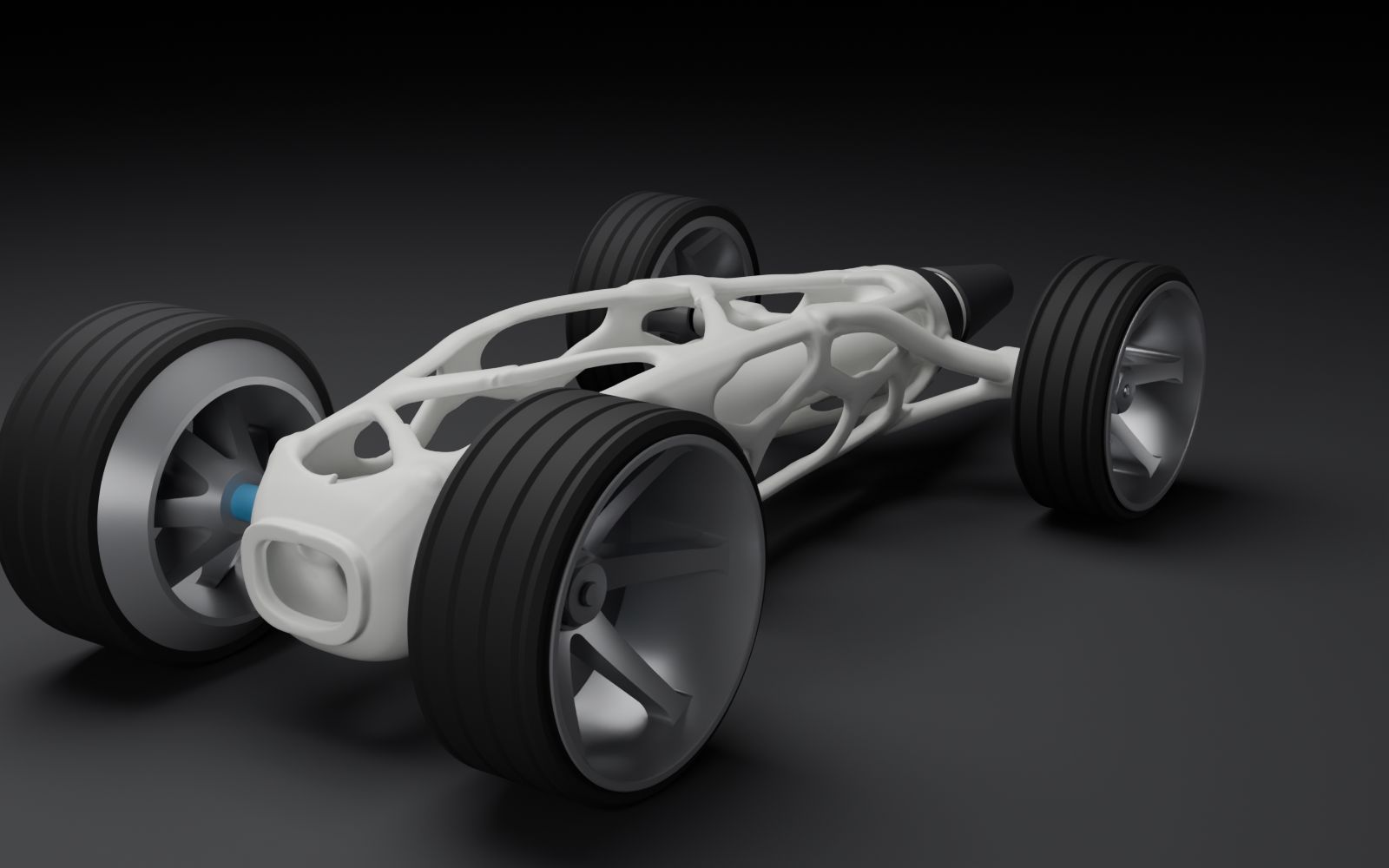
Earnie's rubber band racer: a 3D-printed lattice chassis drawn after a 2015 design-school car, driven by one folded band through a 2:1 pulley.
The brief
Build a car powered by rubber bands. It has to travel at least 5 meters in a straight line, and the longest run wins. Along the way, explain it: the simple machines inside it, Newton's three laws, the friction that slows it, and measured time, distance, velocity, acceleration, mass and force.
Earnie picked the reference: the Cirin, a rubber-band RC car that three Art Center College of Design students (Max Greenberg, Sameer Yeleswarapu and Ian Cullimore) built in 2015. Its frame is a one-piece printed nylon lattice wrapped round a carbon tube, closer to bone than to a kit car.
He directed the design through an AI model, Claude, and named it AIbert. The lattice shapes, the physics model and the print files came out of that conversation; the reference, the name, the colors, the build and the test runs were his. A few years ago a chassis like this was work for a design studio with industrial software. Here it took a weekend of conversation and a shop full of printers.
v1: a flat lattice
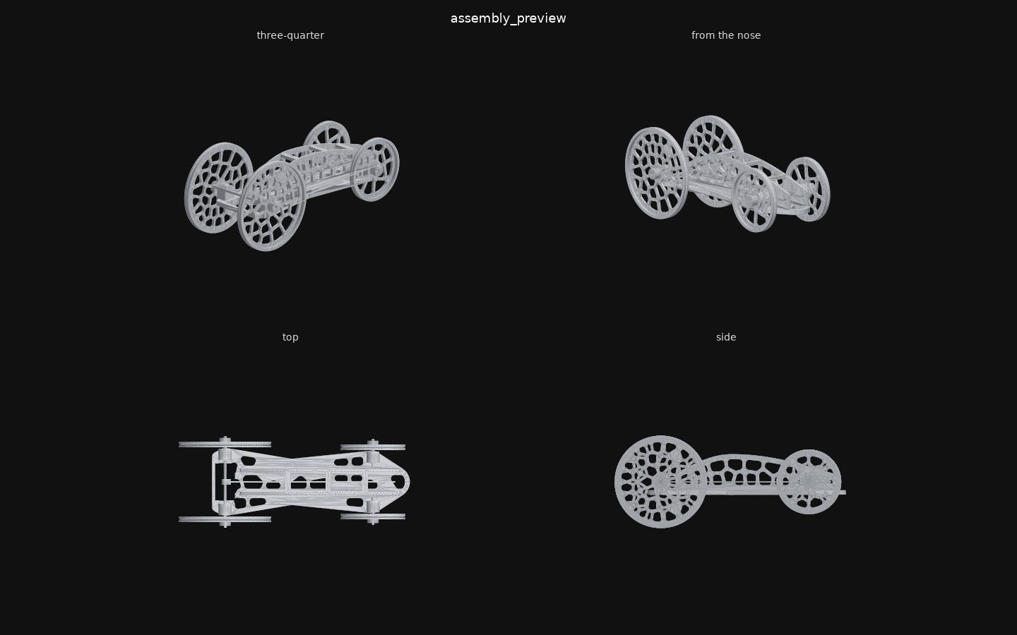
The first version was a flat Voronoi-cell floor with a winding hook on the rear axle, the band hooked straight onto it. On Sept 29 it went through four independent reviews: collisions in the mesh, the drivetrain physics, the print process, and a check against the Cirin itself. Each finding was ranked by how much distance it would cost.
The worst one was simple geometry. The winding hook's tab hit the deck, so the axle could not turn a full circle. Of 57 hook positions checked, none cleared. That car goes nowhere.
The second worst was physics. The band wound onto a 13 mm collar would ask the tires for 2.7 N of push when they can hold about 0.45 N before spinningE. Most of the band's energy would have gone into wheelspin.
| Finding | What it costs | The fix |
|---|---|---|
| Winding hook hits the deck; 0 of 57 positions clear | The car goes 0 m | A 16 mm keep-out round the rear axle |
| Band on a 13 mm collar asks for 2.7 N against 0.45 N of gripE | About 80% of the energy lost to wheelspin | Wind a thin string on the bare 3 mm axle instead |
| Nothing makes the band let go at the end of the run | The axle rewinds it and brakes the car: 30 m falls to 6.6 mE | The string ends in a loop over a short rounded peg, so it slips off |
| Rubber-sealed bearings drag more than printed bushings | 30 m falls to 4 mE | Shielded bearings, degreased |
| Set screws slip on round rod | Wheels spin on the axle | File a flat where each screw bites |
E marks a number from the physics model, an estimate. Real floors give less.
v2: drawn from the inside out
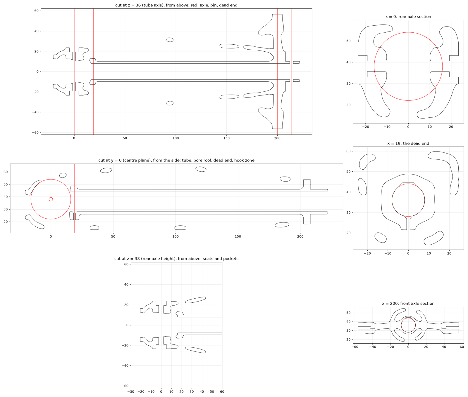
v2 fixed every v1 finding. A braided bio-truss shroud wrapped a printed tube, the band stretched inside the tube, and a string wound onto the bare axle. Every hole line was probed so no strut crossed a pin.
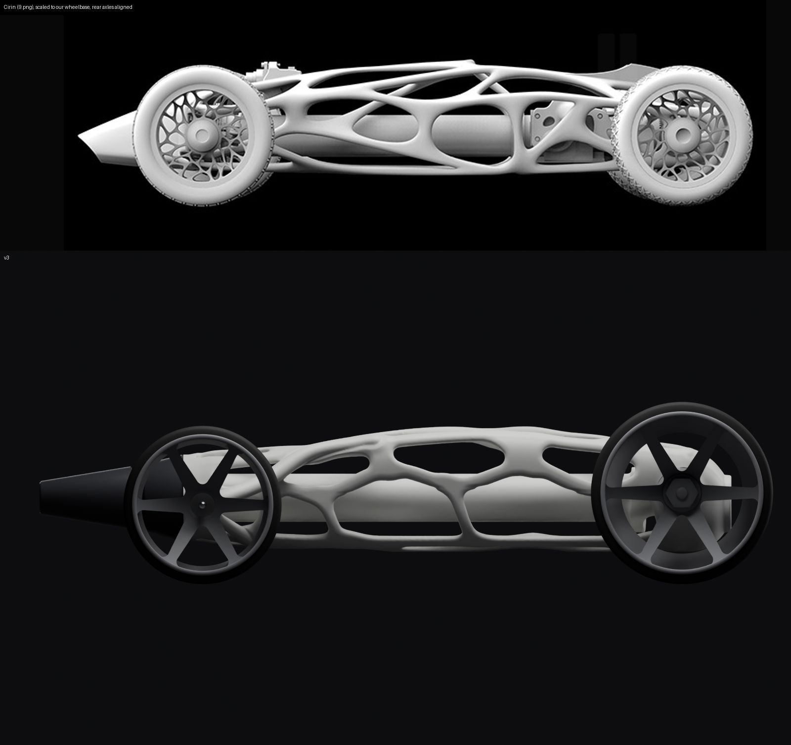
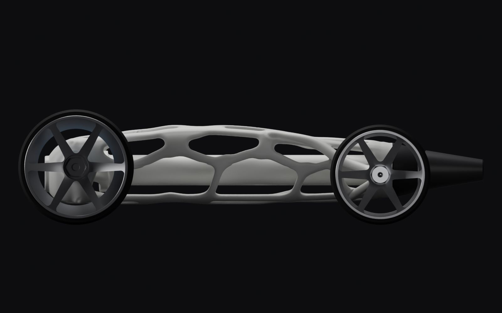
Then, the night of Sept 29, it went beside the Cirin at the same wheelbase, and it lost. It looked like a carrot on wheels of swiss cheese. The numbers said why: the Cirin's wheelbase is about 3.5 tire diameters, v2's was 1.6; its tires are twice as tall as they are wide, v2's were seventeen times; its side view is a long low torpedo, v2's was a cone rising into the middle of the rear wheel.
The cause was the order of work. v2 started with the drivetrain, the tube first, and wrapped a braid round it. The Cirin started with the silhouette.
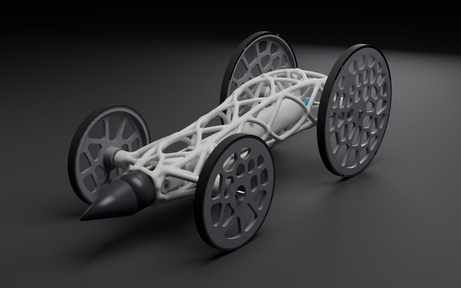
v3: silhouette first
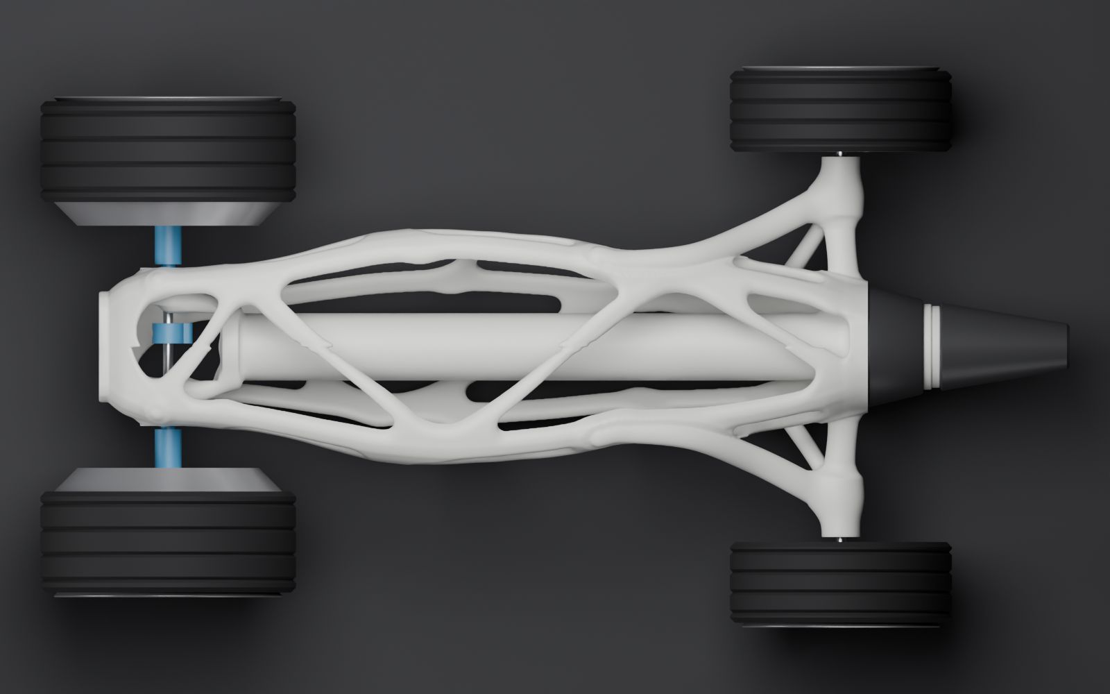
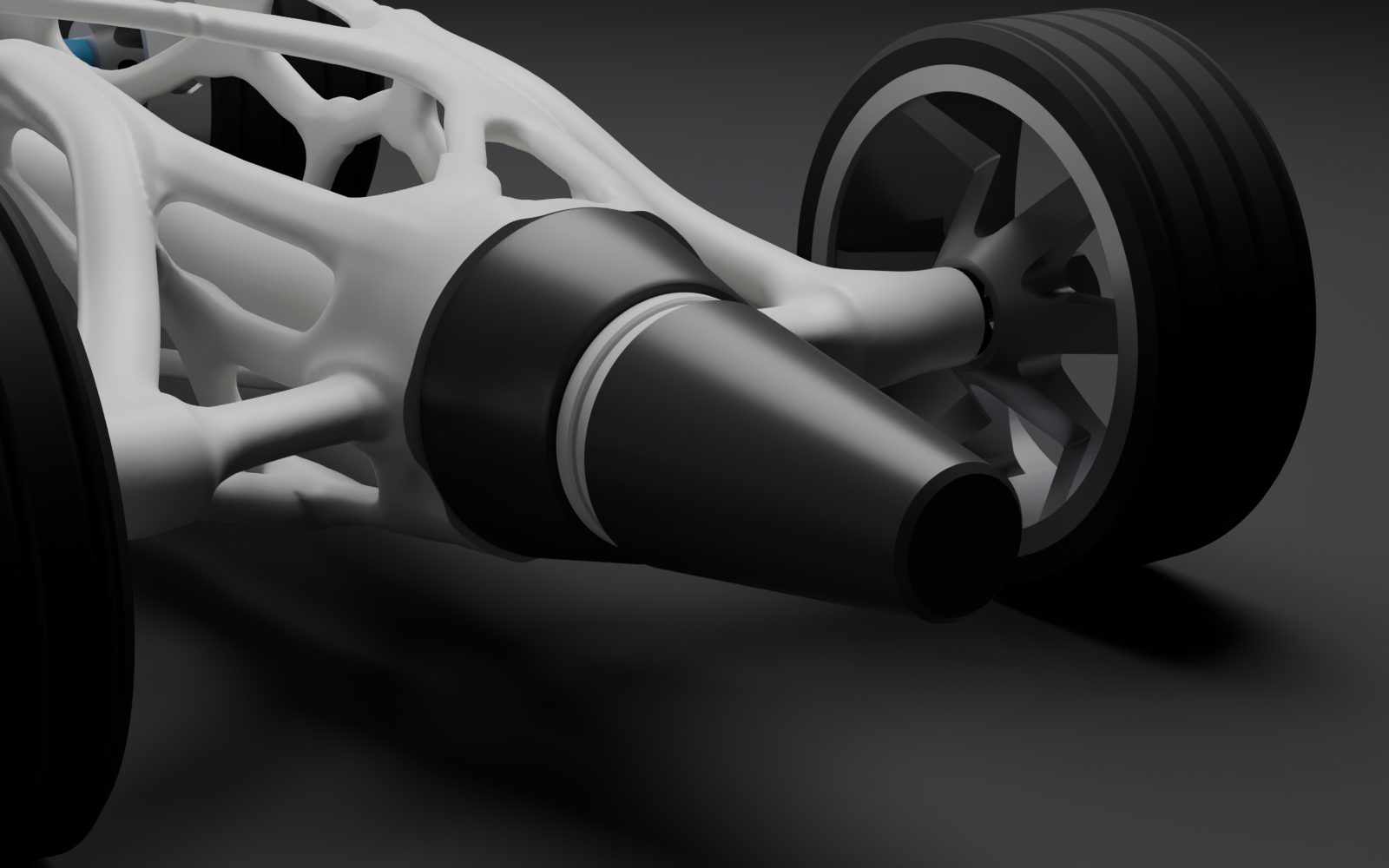
v3 starts with the outline: an F1 stance, a torpedo side profile, and a plan view shaped like a T, with broad arms at the front axle, a narrow waist and a rounded tail. A skin sits just under that envelope, with big lens-shaped openings wherever the loads leave room and tighter cells where they come in.
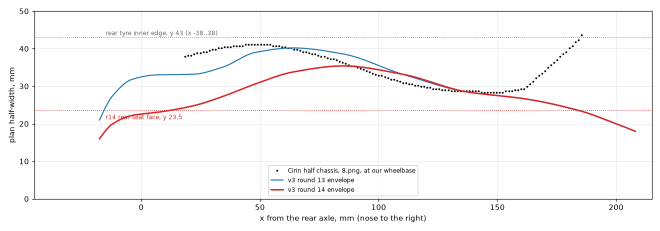
Measured off the Cirin's top view at the same wheelbase, its plan is not a straight taper. It pinches to a waist about 28 mm wide each side, then swells to 41 mm near the rear. That waist and swell is the gentle S-curve in the outline. Round 14 moved the rear seats inward by 11 mm so the rear wheels stand off the body on bare axle instead of packing against a wide tail.
The drive
Grip sets the limit. The floor can only push back on the rear tires so hard: the friction coefficient times the weight on them, about 0.91 N for a car near 300 gE. Any pull beyond that spins the wheels and turns stored energy into heat.
So the band hides inside the spine tube and pulls on a shuttle. A string ties off at the tube's rear mouth, runs forward round a bearing on the shuttle, and comes back out to the rear axle. That is a 2:1 pulley. The axle feels half the band's pull and takes twice the string, which keeps the launch pull under the grip limit and spreads the same energy over twice the distance.
The rear tire is 76 mm across and the axle is 3 mm, so each centimeter of string moves the car about 23 cm. Through the pulley, each centimeter the band shortens moves it about 46 cm.
The string's free end is a small loop dropped over a peg on the axle. When the band runs out, the loop slides off and the car coasts. Without that, the spinning axle would rewind the string the other way and brake the car.
Model distances, one folded #33 band: about 45 mE. Two folded #33s side by side: about 74 m, with launch pull still inside the grip limitE.
Printing it
The parts printed over two days on whichever machine was free, and most of the print decisions got made by what broke.
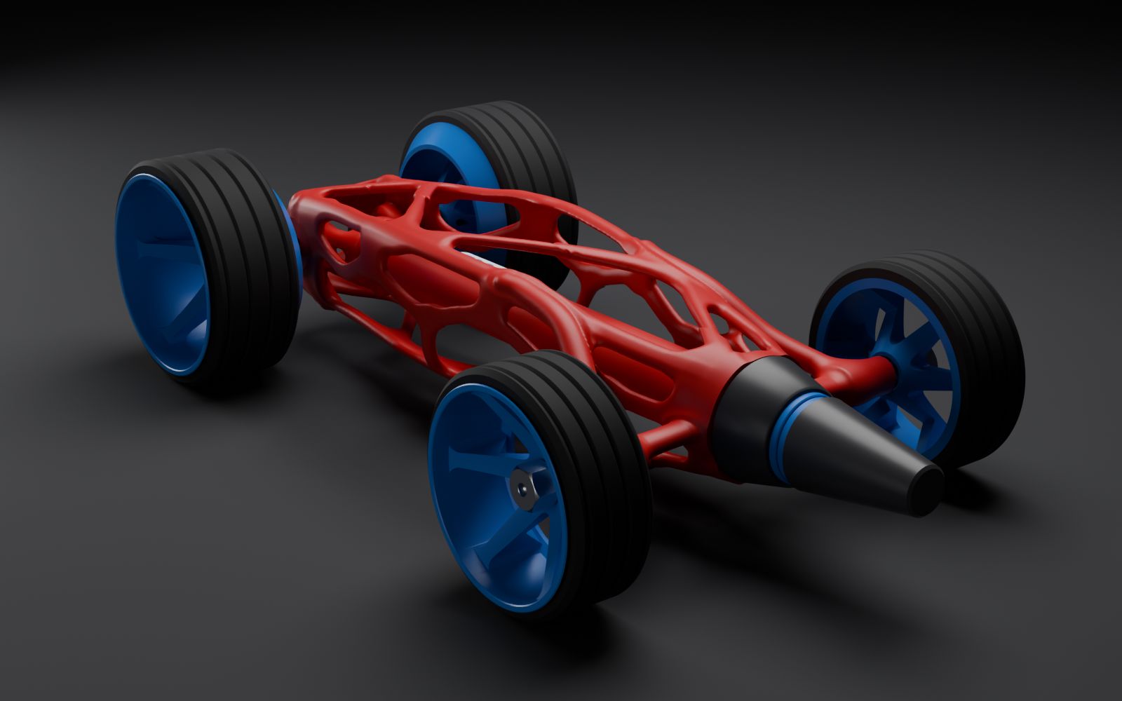
- The chassis planOne piece on a Stratasys F170 in ABS, with support that dissolves in a heated sodium hydroxide bath. The machine had red ABS loaded, so Earnie chose his colors around a red body: blue wheels and nose rings, a white badge.
- DroppedThe support bath turned out empty, with no solution on hand. The F170 route went. The chassis moved to a Bambu X1C in PLA, with tree supports.
- The support fixHand-picking PLA tree supports out of a lattice is slow and tears the part. The fix was a PETG layer where each support touches the chassis. PLA does not bond to PETG, so the supports lift off clean. The cost: 244 filament swaps and a print that grew from 7 h 27 m to 13 h 42 m.
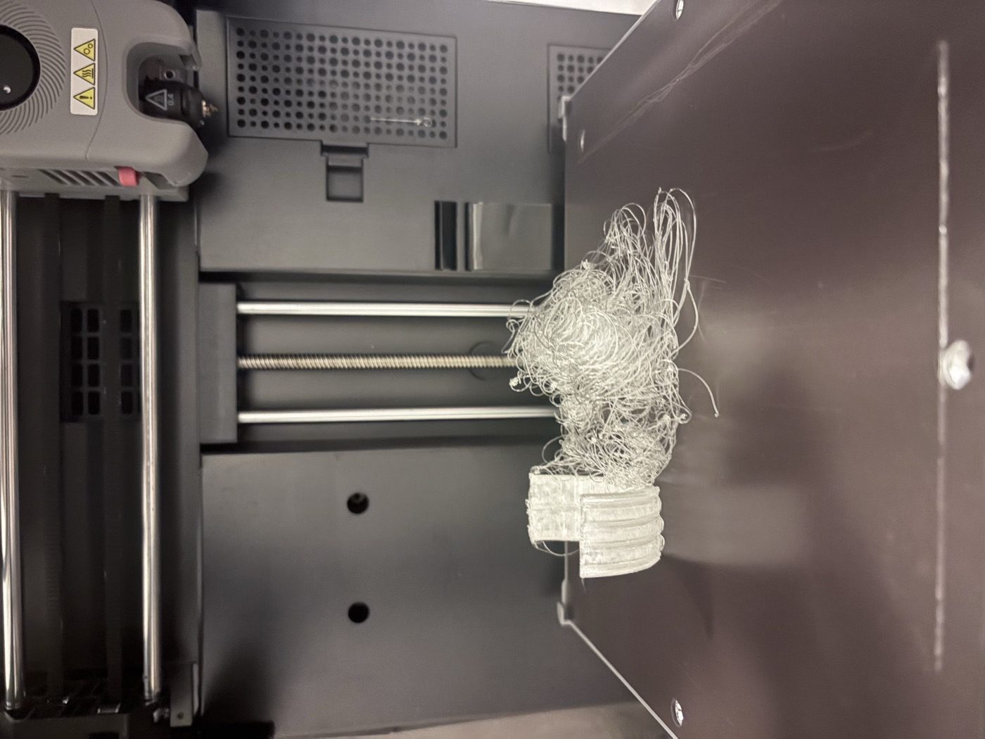
- Wheels, attempt oneLightweight foaming PLA with a blue lip. The rear wheels came off the bed mid-print and balled filament round the nozzle. The cause was a small footprint holding a 38 mm tall part, no brim, heavy cooling and a cool bed. Reprinted in plain black PLA with an 8 mm brim and a hotter bed; both printed clean.
- Tires, a spareA spare tire sliced standing on edge tipped over at home. Lesson kept in the files: tires print flat.
- BearingsThe online bearing order was canceled and no local store stocked them. Seven bearings came out of idler pulleys in a spare-parts bin. They were 693s, 8 mm across, where the pockets were drawn for 10 mm 623s, so printed adapter rings make up the gap.
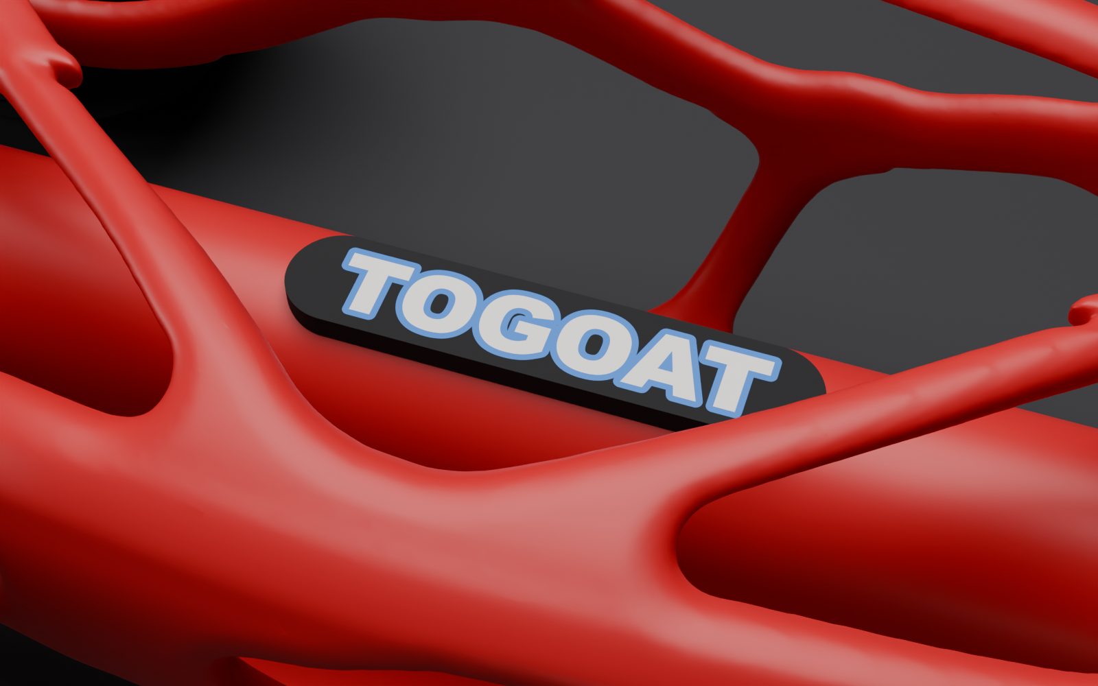
- BadgeRoyal blue letters on matte black rendered fine and read badly in person: two dark colors at about 2:1 contrast. The badge went to white letters with a thin blue keyline.
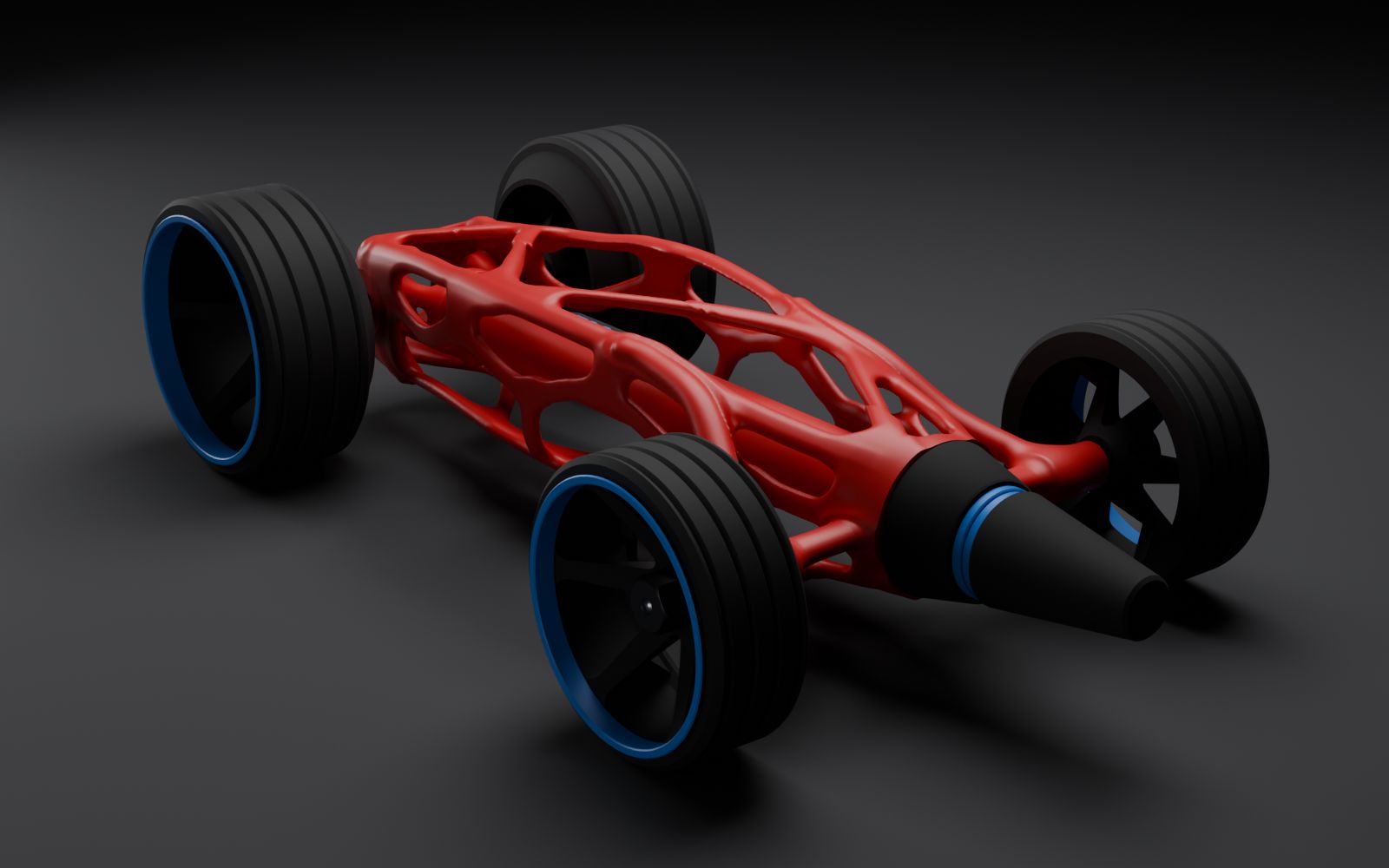
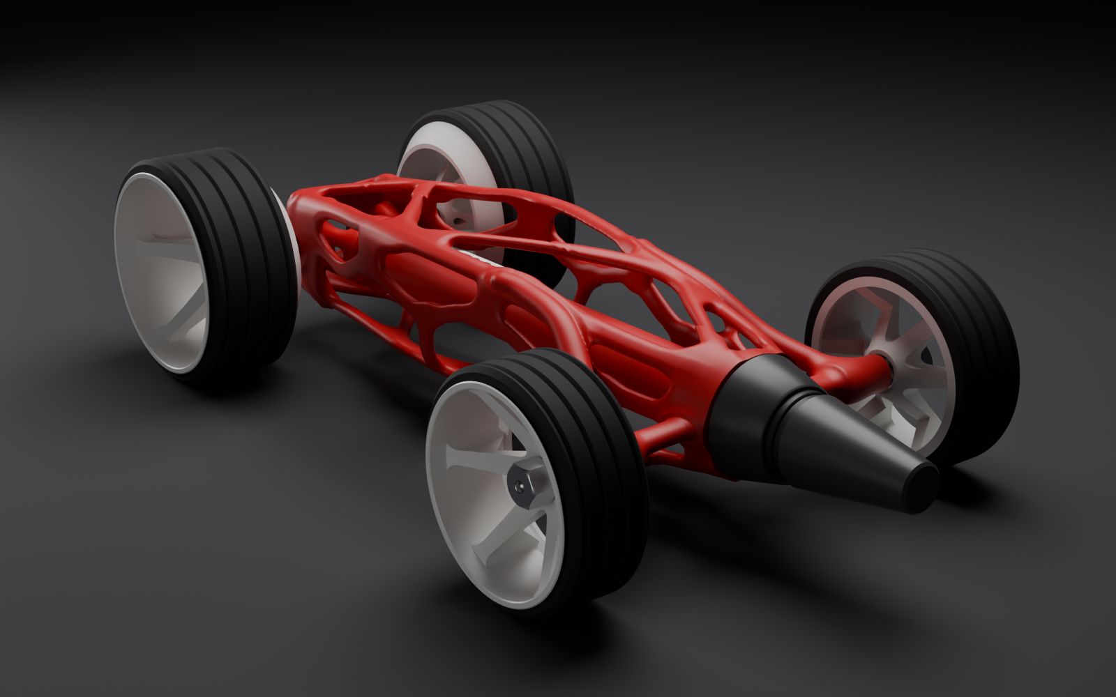
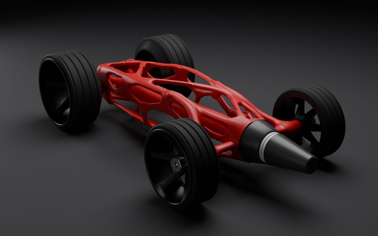
Colorways Earnie weighed
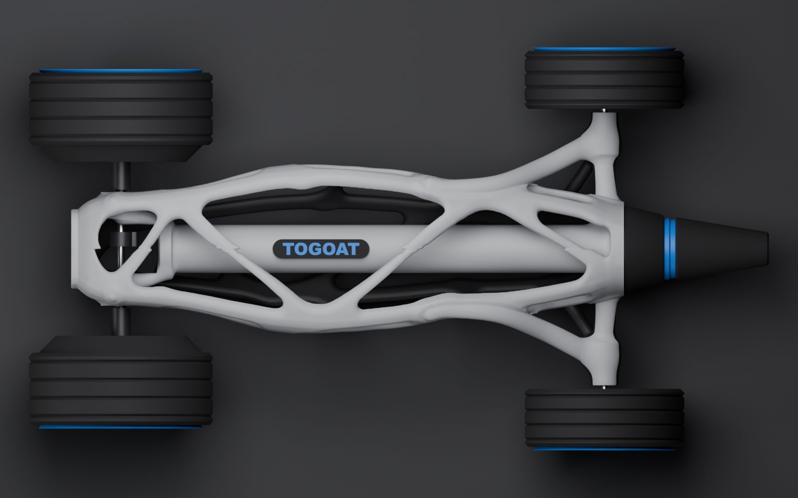
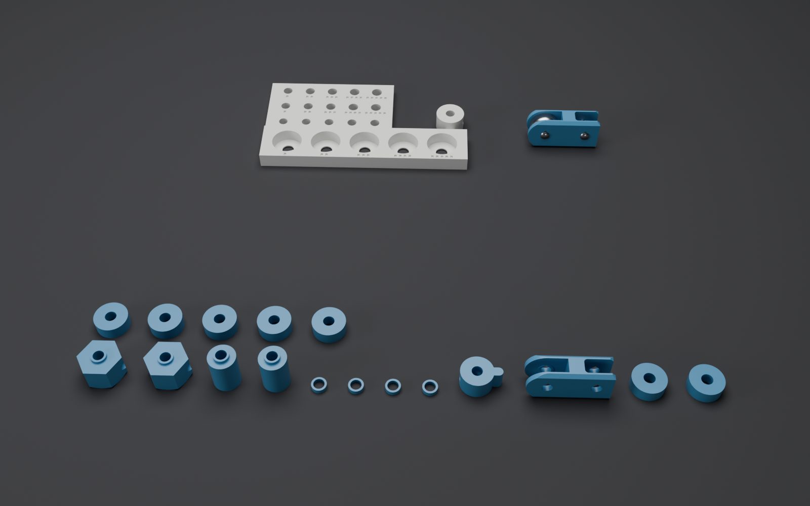
The build
Twelve steps, in this order: clean the supports off the chassis; glue the nose stack; seat the badge; press the rear bearings into their adapter rings; stretch the tires on and seat the front bearings; mount the front wheels on pressed-in stubs; thread the rear axle through wheel, sleeve, bearing, drive peg, bearing, sleeve, wheel; spin-test every wheel; load the shuttle with its band and string; pin the band, tie the string's dead end and drop its loop over the peg; release-test with the wheels in the air; then floor runs along a tape line, one change per run.
The night before
The car was built by Thursday evening. It did not go.
- First testThe fishing line tangled on the axle and the car barely moved. Nothing held the winds in place on a bare 3 mm rod, so the line walked and knotted.
- A spoolA snap-on spool for the axle was modeled and sent to a red team before printing. It found two weak points, so it became a sealed, press-fit spool instead. Measured against the CAD, it only fit on one side of the peg.
- Wound by handBefore the spool printed, a hand-wound test: the car crawled about two feet and stopped, with the tension gone. Fine with the wheels in the air, dead on the floor.
- By eliminationEvery rotating joint is a fit on smooth steel rod, and a photo of the axle showed monofilament on bare polished steel with nothing to grip, plus a strand that had sprung out through the lattice. Those were real, and none explained a car that ran in the air.
- The likely answerThe design calls for one #33 band, doubled: folded in half, four strands, a 4.5 cm loop across a 4.5 cm gap between the nose pin and the shuttle. The car had two bands, unfolded. A 9 cm loop across that gap is slack for the last third of the shuttle's travel, and pulls about half the designed force for the rest.
One word, doubled, read two ways, cost the whole night.
The fold costs nothing and the design assumes it, so it went first on race morning. The other live suspect was a wheel slipping on its axle under the car's weight. A sharpie line across each rear hub and onto the axle tells the two apart: if the marks split after a run, the hub slipped.
The lesson for the next build doc: say exactly what doubled means.
Race day
? m
Friday Oct 2, 2026. Measured distance goes here after the run.
| Run | Change made | Distance (m) | Time (s) | Avg velocity (m/s) |
|---|---|---|---|---|
| 1 | ||||
| 2 | ||||
| 3 |
Model prediction for comparison: 45 m on one folded bandE. The minimum is 5 m.
Files
- Interactive build book3D, every step
- Drive model3D, the 2:1 pulley
- STL downloads and TinkerCAD importEvery part, registered
- Whole car, one zipSTL
- The Cirin, by its designersBehance, 2015